To build a 5-band stereo graphic equalizer, five stereo "slide potentiometers" are used, but a rotary potentiometer is used here; only for this reason should it be called 5-channel tone control. You can build a five-channel graphic equalizer by following the circuit diagram below.
- Reckless Bass Boost Capacity
- Smooth bass, controlled sound
- Excellent Midrange Frequency Audio Controller
- The world-famous
• Project Name- 5 Band Graphic Equalizer or 5 Channel Audio Tone Controller.
Sanyo, a Japanese company, makes an audio-graphic equalizer using the LA3600 IC. The internal schematic circuit inside that IC uses 5 NPN transistors and an operational amplifier or op-amp IC 4558. This schematic circuit diagram I designed follows that circuit diagram strictly. I have built many commercial graphic equalizers with this schematic circuit diagram.
This graphic equalizer's performance is unique, with crystal clear sound quality and excellent tone-controlling capacity. The LA 3600 IC is a monophonic graphic equalizer IC, so two ICs are used in the stereo sound system. To make this five-band graphic equalizer with transistors, you need to make a board with ten transistors; that is, you have to make a double circuit on a PCB (for a stereographic equalizer or tone controller).
Microphone Preamplifier Circuit Diagram Circuit Diagram
H2 5 Channel Audio Tone Control Board
• Operating Voltage- Dual Power +12V GND -12V, or +18V GND -18V
• Frequency -108Hz, 334KHz, 1Khz, 3.43KHz, 10KHz
5 Channel Stereo Tone Controller Schematic Circuit Diagram Using Transistor and 4558 IC
5 Channel Stereo Audio Tone Control Board Using 10 Transistors & 4558 IC.
The figure below shows a schematic circuit diagram of a five-band graphic equalizer or five-channel tone controller. It requires ten C2120 or BC547, or equivalent NPN transistors, and a 4558 dual op-amp IC.
This schematic circuit diagram is a high-performance graphic equalizer or audio tone control. Its high-pass filter, low-pass filter, and two more categories of mid-range audio frequency control capabilities are unmatched and of very high quality. This graphic equalizer's Bass Boost system and Treble control are fantastic.
 |
5 Band Stereo Graphic Equalizer Schematic Circuit Diagram Using 4558 |
Components List -
Q1, Q2, Q3, Q4, Q5 = C2120 NPN Transistor or equivalent.
U1 A and B = 4558 Op-amp IC
R1, R2, R3, R9, R10, R11, R12, R13 = 4.7KΩ
R3, R15, R16, R17, R18, R19 = 68KΩ
R4, R5, R6, R7, • R8 = 1.2KΩ. • R22 = 10KΩ
R20 And R21 = 470Ω For +12V GND -12V Dual Power Supply
1.2K For +18V GND -18V Dual Power Supply.
3.3KΩ For +30V GND -30V Dual Power Supply.
C1= 3.3µfd • C2= 102 • C3= 392 • C4= 103 • C5= 392 • C6= 112 • C7= 471
C8= 684 • C9= 224 • C10= 682 • C11= 223 • C12= 682
C13, C14 = 220µfd • C15, C16= 104 • C17= 2.2µfd • C18= 22µfd
RV1, RV2, RV3, RV4, RV5, RV6= 100KΩ.
( All capacitors are not less than 25 volts)
D1, And D2= 6V Zener Diode
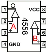
Note: The IC indicated as U1 in the circuit diagram is a KA4558 Op-amp IC. Pins 1, 2, and 3 of this IC or the A part must be used to build a 5-transistor mono graphic equalizer or tone control board and pins 5, 6, 7, or the B part should be used for the 10-transistor stereo graphic equalizer or tone control board.
Video Tutorial for Making 5 Band Stereo Tone Control or Graphic Equalizer with 4558 IC and 10 Transistors.
.jpg)


No comments:
Post a Comment