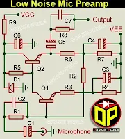
Microphone Preamplifier Circuit Diagram using Transistor: To get a crystal clear sound from the loudspeaker, we need a high-performance microphone preamplifier module capable of receiving and outputting all signals in the audio frequency range of 20Hz to 20KHz.
Here is the circuit diagram of the microphone preamplifier, which can provide a low-noise audio signal output for condenser/electret microphones or dynamic microphones.
Low Noise Microphone Preamplifier Schematic Circuit Diagram
This microphone preamplifier circuit is suitable for dynamic microphones of 600Ω to 1KΩ impedance and will also provide excellent performance for condenser microphones. Refer to the complete guidelines to build this microphone preamplifier board according to your requirements.
 |
| Microphone Preamplifier Circuit Diagram |
Components Value For Mic Preamplifier Circuit-
TR1, and TR2 - BC547 or C2120 NPN Transistor, D1 - 8.2 Volt Zener Diode.
R1 - 4.7KΩ, R2 - 100KΩ, R3 - 47Ω, R4 - 56Ω, R5 - 3.3KΩ, R6 - 1KΩ, R7 - 1.5KΩ, R8 - 1KΩ,
R9 - 1KΩ for 12V Circuit, 3.9KΩ for 24V Circuit.
C1 - 1µF, C2 - 220PF, C3 - See below, C4 - 22µF, C5 - 2.2µF, C6 - 220µF, C7 - 330PF
C3 is 10µF for dynamic microphones and does not need to be installed for condenser or electret microphones.
Some Tips for Getting the Best Performance from Microphone Preamplifier Circuits:
• The negative supply of this mic preamp circuit board cannot be taken from the main audio output section; it must be soldered to the front body of the metal cabinet.
• A wire from the ground section of the audio output amplifier circuit should be soldered to the rear of the metal cabinet.
• No ground connection should be provided in the middle of the cabinet.
• The ground connections of the microphone socket should be connected very close to the input section of the mic preamp circuit.
• A mic preamp circuit board should be placed in the front of the cabinet, and the audio output amplifier board or components and power transformer should be placed on the backside.


No comments:
Post a Comment