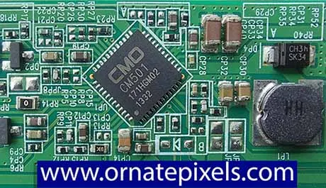
• Number of the Integrated Circuit - CM501
• Application- LCD Panels power management (PMIC)
• Type of package- WQFN (Quad Flat No Lid)
• Number of terminals- 12 x 4 = 48
• Operating voltage Vin- Minimum 8 volts to Maximum14 volts
• Oscillation frequency of Boost & Buck Converter- 20Mhz
• Temperature tolerance -40°C to +85°C
• Internal N Channel MOSFET - 20V, 3.5 Amp, 01.Ω
CM501 IC can be used in devices with large-size TFT (Thin Film Transistor) display panels, such as LCD TVs, computer monitors, laptop displays, etc.
The internal boost and buck converter circuit arrangement of CM501 IC has overcurrent protection and a thermal shutdown system, which can provide a safe power supply to the gate driver circuit, source COF, and all thin film transistors of TFT display panels.
The CM501 IC has internal N-channel MOSFETs to boost and buck voltage output, which is used for low power consumption. VGH voltage is output through the VGH charge pump regulator, and VGL voltage is output from the VGL charge pump regulator. These VGH and VGL voltages are used as gate bias voltages of the TFTs, and that voltage is controlled by the gate COF (Chief on Film).
CM501 IC Schematic Circuit Diagram Pinout
Schematic Circuit Diagram of CM501 IC
 |
| CM501 IC Schematic Circuit Diagram and its pinout |
The CM501 IC contains the Get Pulse Modulator (GPM). A programmed over-current protector system, high-voltage low-dropout regulator (HV LDO), voltage detector (XAO), and VCOM voltage output supply the source terminals of millions of thin-film transistors to automatically control image contrast. For more information, see and understand the schematic circuit diagram of the CM501 IC.
Various LCD panel manufacturing companies have used the CM501 IC in their manufactured LCD panels. CM501 IC is used in the DC-to-DC converter or power management stage of the Innolux LCD TV panel. Below is a picture of the DC-to-DC converter section with boost and buck converter, which uses CM501 IC.
Some Tips Regarding CM501 IC Replacement for LCD TV Technicians
Since the CM501 IC has built-in overload protection, short circuit protection, and over-voltage and under-voltage detection circuits, the CM501 IC is not easily damaged. If the VGH, VGL, and AVDD voltages are not output, in most cases, it should be understood that there is a short circuit or over-current following in the panel's Source COF or Gate COF or COG. So, before changing the CM501 IC, the LCD panel should be checked to see whether there is any problem.
Also, if the required voltages are not output from the circuit used CM501 IC, the capacitor diode transistors should usually be checked by following the circuit diagram above.
Equivalents or substitutions of CM501 IC
The pin configuration of the CM501 IC is precisely similar to the following ICs.• 6861AAQ
• RT9955
• 5562A
These three ICs will likely be substituted for CM501 IC.
Here is the P301-16 IC Schematic Circuit Diagram

No comments:
Post a Comment